Structured Fiber Cabling Solutions for Network & Server Cabinet
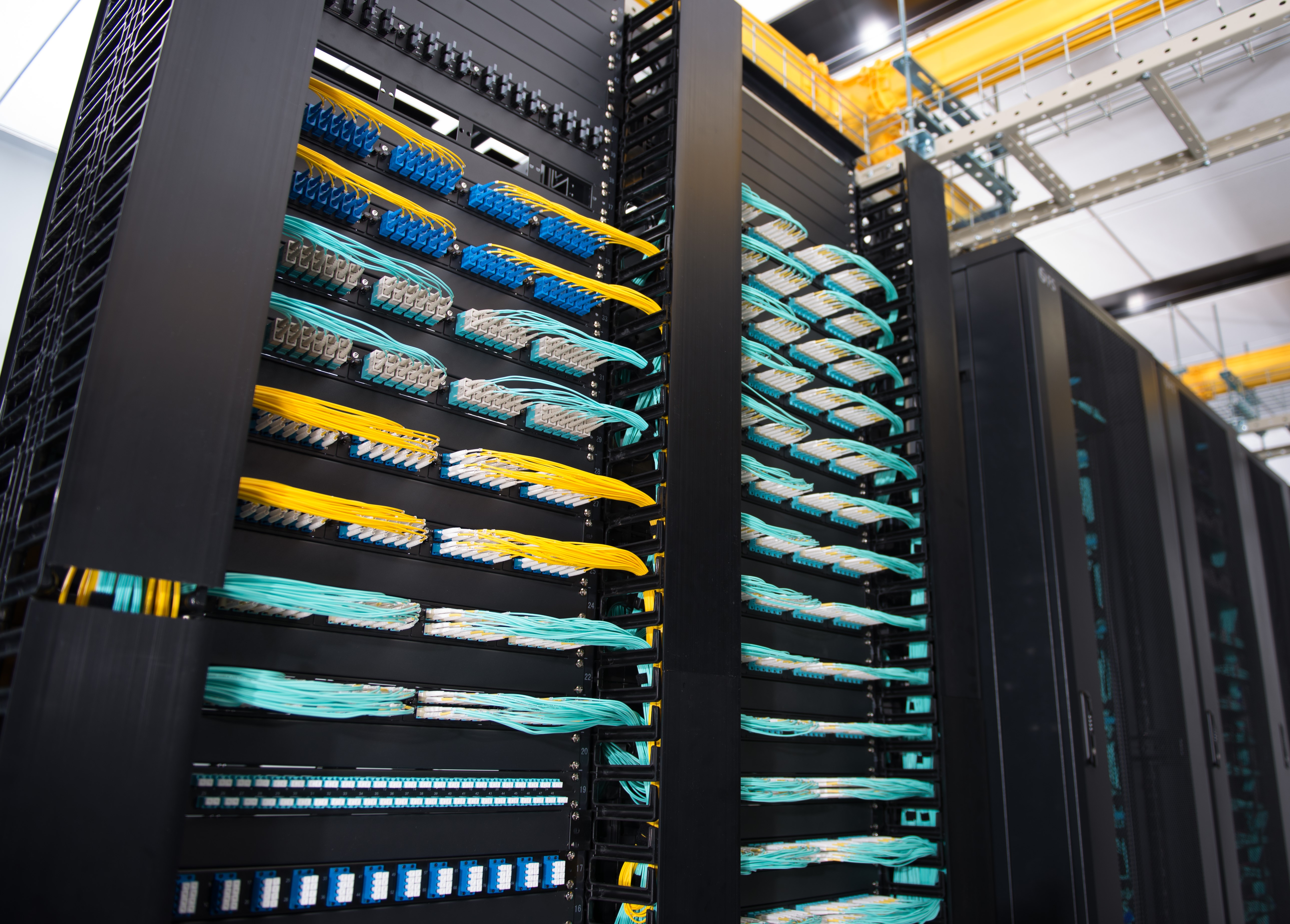
How does your network or server cabinet look like? Are they stocked with varied servers or networking equipment connected with long cables that reach out to the devices on the other cabinet or enclosure? This is exactly what we used to call point-to-point cabling. However, it is also an art to keep a neat cabling. This article unveils a compelling new cabling method—structured fiber cabling solutions for network&server cabinet.
What Is Structured Cabling and How Does It Matter?
In recent years it has become apparent that fiber-optics are replacing copper wire as an appropriate means of communication signal transmission. The standardized architecture and components for communications cabling formulated by the EIA/TIA TR42 committee—structured cabling is used as a voluntary standard by manufacturers to ensure fiber-optics interoperability. In a structured cabling system, a variety of patch panels and trunk cables are harnessed to create a structure that allows for hardware ports to be connected to a patch panel at the top of the server rack. That patch panel is then connected to another patch panel via a trunk (multi-fiber assembly designed for use in conveyance) in the MDA (Main Distribution Area). When you have several servers, with multiple patch connections and power cords running through your server rack, you need to keep them arranged and managed with an excellent rack cable management system. 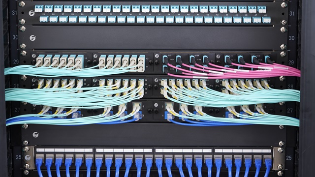
Here some may wonder why bother to cost more on the connecting gadgets? Well, without running long patch cords from equipment racks, MACs are much quicker as the cable and port tracing becomes a much easier job. The potential for downtime goes down with the reduced potential for human error. A structured cabling system will look aesthetically pleasing.
Structured Fiber Cabling Solutions for Network & Server Cabinet
In the server room, there may be a server cabinet and a network cabinet for the storage of routers, patch panels, switches and a wide variety of networking equipment as well as networking accessories. Taking FS GR600-series server cabinet and GR800-series network & server cabinet housing 10G and 40G applications as an example, let’s see an exemplary structured fiber optic cabling.
Server Rack to Network Rack
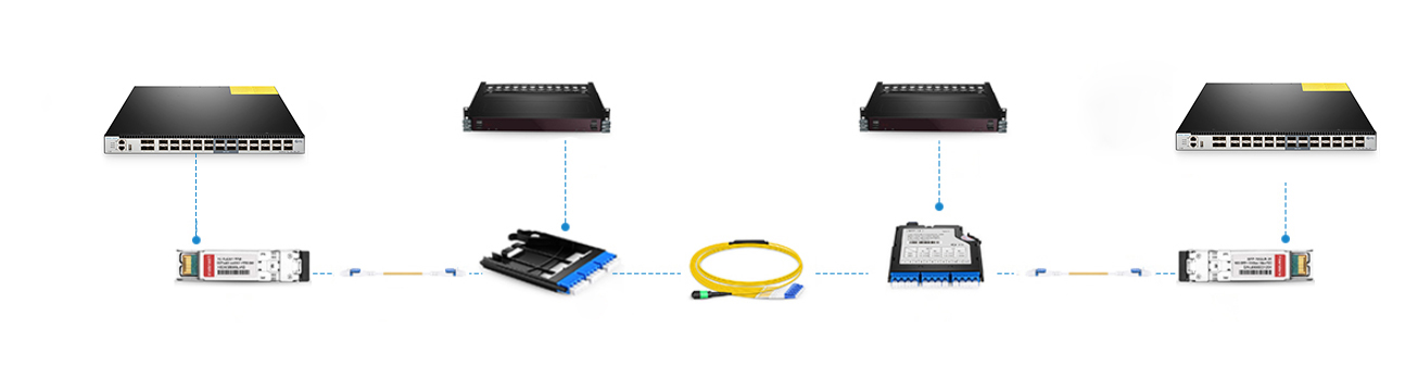
As for intra-rack cabling, say server rack to network rack (10G-40G), connect the 10Gbe switch to a MTP-8 MTP/MPO breakout cassette via a 10GBASE-SR SFP+ transceiver and an LC fiber optic patch cable. Then bridge the cassette with fiber adapter panel which is finally linked to the 40Gbe QSFP+ uplink port on a 10Gbe switch through the MTP trunk cable and a 40GBASE-SR4 QSFP+transceiver. In this respect, the centralized cabling solution keeps cables organized and out of critical airflow paths.
Network Rack to Core Rack
When it comes to network rack to core rack (40G-40G), connect the 40Gbe QSFP+ uplink port on a 10Gbe switch to the FS ultra high density fiber adapter panel with 6 MTP adapters through the MTP trunk cable and a 40GBASE-SR4 QSFP+transceiver. Then draw together two same adapter panels together via an MTP trunk cable. Finally, link the second adapter with the 40Gbe switch by the 40GBase-SR4 QSFP+ MTP/MPO transceiver module and MTP trunk cable. In this way, you can save much energy on tracing each devices.
Rack Cable Management
To realize a structured fiber optic cabling for server cabinet, rack cable management is crucial. FS also provides FHD blanking fiber adapter plate, 1U metal horizontal lacer panel with 5 rotating and detachable plastic D-rings, 1U rack blank panel, colorful T type magnetic velcro cable tie and P type adhesive label paper sheets.
Conclusion
Structured cabling systems use various product sets, like fiber optic trunks and fiber optic enclosures, to create an easy-identifying, good-looking, ordered cabling infrastructure. FS boast various tools positioned as structured cabling solution for network & server cabinet.
FS.COM N5850-48S6Q VS. Cisco Nexus 3172PQ 48-Port 10Gbe Switch
What do you care most about a data center switch? The number of ports? The switch class? Or the operating system? Here is a comparison of two 48-port 10gbe switches from FS.COM and Cisco. Let’s see what the vendors value for their own devices?
FS N5850-48S6Q 48-port 10Gbe Switch Overview
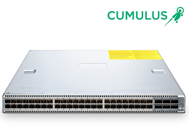
FS N5850-48S6Q network switch is initially positioned as the bare metal switch, but you can choose the one pre-installed with Broadcom ICOS or Cumulus Linux. The combination of Cumulus Linux makes the N5850-48S6Q 10gbe switch stand head and shoulders above its counterparts. Here we revolve around the one with Cumulus Linux. FS N5850-48S6Q network switch comes with 48 SFP+ 10Gb ports and 6 QSFP+ 40Gb ports, and each 40Gb port can operate in native 40-Gbps or 4 x 10-Gbps mode. N5850-48S6Q is a top-of-rack (TOR) or leaf 10Gbe switch in a compact 1U form factor, ideally suited for high performance and programmable data center environments. It performs excellent low latency and power efficiency in a PHY less design while providing high-reliability features such as redundant and hot-swappable power supplies and fans in forward and reverse airflow configurations. The switch supports advanced features such as MLAG, VxLAN, SFLOW, SNMP, MPLS etc, making it ideal for traditional or fully virtualized data centers.
Cisco Nexus 3172PQ 48-port 10Gbe Switch Overview
The Cisco Nexus 3172PQ switch is a dense, high-performance 10gbe and 40 Gigabit Ethernet switch. Externally, it shares the same port configuration and 1RU form factor with FS N5850-48S6Q 48-port switch. Internally, it runs the industry-leading Cisco NX‑OS software operating system, providing customers with comprehensive features and functions that are widely deployed. It supports both forward and reverse (port side exhaust and port side intake) airflow schemes with AC and DC power inputs. Dual redundant power supplies make it possible for the switch to run with a single power supply and with one failed fan module. The switch also has a serial console port, a USB port, and an out-of-band 10/100/1000-Mbps Ethernet management port.
48-Port 10Gbe Switch Comparison
FS N5850-48S6Q Vs Cisco Nexus 3172PQ Basic Configuration
| Items | FS N5850-48S6Q | Cisco Nexus-3172PQ |
| Ports | 48*10Gb+6*40Gb | 48*10Gb+6*40Gb |
| Switching Capacity | 1.44Tbps Full-duplex | 1.4-Tbps |
| CPU | Intel Rangeley C2538 2.4Ghz 4-core | 1.5 GHz Intel Processor(dual core) |
| Forwarding Rate | 1 Bpps | Up to 1 Bpps |
| Jumbo Frame | 9000 Bytes | 9216 Bytes |
| Dimensions (WxDxH) | 433.8 x 520 x 43.8 mm | 439 x 432 x 44 mm |
| Price | $5799 | $8,487.12 |
FS switches, generally, have the switching ports on the front panel. Oppositely, Cisco Nexus 3172PQ switch ports are at the rear side. As for the central processing unit (CPU), FS N5850-48S6Q boasts four core and more cores will make your processor faster overall. The switching capacity, the aggregate capacity of all switch ports, is often a measure of the switch’s fabric bandwidth and the switch’s packets per second forwarding capacity. FS 1.44Tbps and Cisco 1.4 Tbps are about the same. The table shows a sharp difference in the cost, you can save more on the FS N5850-48S6Q and invest on cabling or other devices.
FS N5850-48S6Q Vs Cisco Nexus 3172PQ: Performance
Network Operating System
The operating system acts as an interface between the hardware and the programs requesting I/O. Cisco Nexus 3172PQ 48-port switch are shipped with Cisco NX-OS network OS. You will have an operating system based on Linux, however, you interact with a management layer that hides Linux and the guts of the system from you. It is hard to make some changes. Cumulus Linux on the other hand isn’t based on Linux, it is Linux. It was not long ago that Cisco proposed the segregation of hardware and software. The technology may not be full-fledged. Cumulus Linux is the only solution that allows you to affordably build and efficiently operate your network like the world’s largest data center operators, unlocking vertical network stacks.
At present, FS N5850 10gbe switch and Cisco 3172PQ are endowed with automation brought by Cumulus Linux and Cisco NX-OS respectively. Automation can replace the laborious manual workflows in configuration changes and upgrades, and also troubleshooting. One facet worthy of mentioning is that Cumulus Linux can seamlessly be applied to varied hardware, which outweighs Cisco NX-OS that is specialized.
Key Features
FS N5850-48S6Q 48-port 10gbe switch supports Ethernet VPN (EVPN) that enables you to connect dispersed customer sites using a Layer 2 virtual bridge, Virtual routing, forwarding (VRF), and Lightweight Network Virtualization (LNV) for deploying VXLANs without a central controller on bare metal switches. Complete Layer 3 unicast and multicast routing protocol suites are supported by Cisco Nexus 3172PQ 10gbe switch, including Enhanced Interior Gateway Routing Protocol (EIGRP) used on a computer network for automating routing decisions and configuration, Routing Information Protocol Version 2 (RIPv2), and Protocol-Independent Multicast sparse mode (PIM-SM).
Conclusion
Cisco Nexus 3172PQ and FS N5850-48S6Q are both 48-port 10gbe switch suited for data center with robust performance and outstanding configuration. N5850-48S6Q network switch is entitled with three different forms for customers. Bare metal switch, bare metal switch with Broadcom ICOS or Cumulus Linux. That’s the great flexibility FS.COM provides with clients.
ONIE: Why It Is Special for Bare Metal Switch?
Have you ever wondered that one day you could customize switches like the way you configure your own PC? It is actually happening. As vendors researches and develops switch structures by decoupling software from hardware, bare metal switch come into being. The switching technology can be programmed like Cumulus Linux servers. They may appear in a lot more average enterprises in the next few years with ONIE moving into the spotlight.
Clearing the Fog Around Bare Metal Switch
Bare metal switch, also known as white-box switch, is solely a switch box with a chip inside it. What makes it differ from original network switch? Well, common Ethernet switches, also called closed switches, are sold with hardware and software together. That is to say, if you buy a Juniper EX or MX series network switches, you also buy JUNOS; if you buy a Cisco Catalyst network switch, you have to buy Cisco IOS. This is in contrast to bare metal switches which widen the choice available to network buyers. They can choose components like application, network OS, and driver, depending on their own needs. The segregation of hardware and software fulfills the vision of a more affordable, manageable network and saves the time and funding for more projects, which is really beneficial to business.
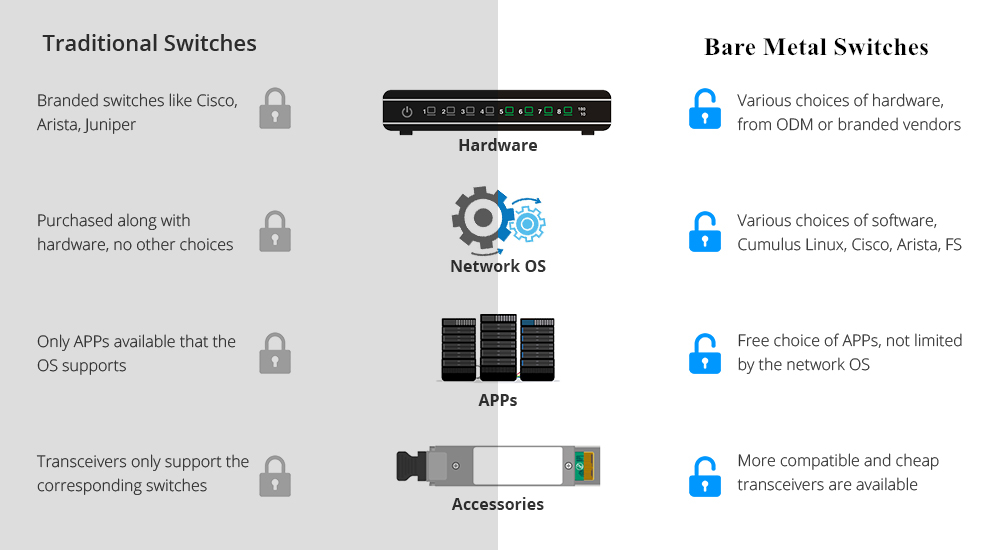
With a cheap bare metal switch in hand, what about the network operating system? That’s what ONIE (Open Network Install Environment) can do for bare metal switch.
Ins and Outs of ONIE
Introduced by Cumulus Networks, open network install environment (ONIE) combines a boot loader and a small linux operating system. Having been pre-installed on bare metal switches where software and bare-metal hardware are sold separately, customers can freely choose network OS from a range of sources over a network using IPv4, IPv6 and TFTP, or even locally from a USB flash drive. ONIE enables switch hardware suppliers to manage their operations based on a small number of hardware SKUs, enabling a thriving ecosystem of both network hardware and network OS alternatives.
ONIE Paving the Way of Bare Metal Switch
With ONIE, consumers can run any compatible network OS, such as cumulus linux Pica8, and Open Source on the bare metal switch, which dramatically reduces the overall capital and operating cost and breaking through the proprietary traditional network architectures. Moreover, switch & network OS vendors can concentrate on researching and developing switches and operating systems, without being distracted by the minutiae of loading a network OS onto a specific switching platform.
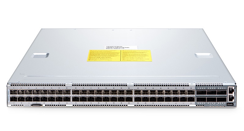
As a component of the open hardware switch platform, ONIE will contribute to advancing standards that define the hardware/software interface. It has now been pre-installed on many bare metal switches, such as FS N8500-48B6C 100gbe switch which also supports current and future network requirements, including an x86- based control plane COM-E with BMC and Timing options for easier integration of automation tools familiar to server administrators. The increasingly mature bare metal switch will in return spur the ONIE to open its arm to more excellent network OS.
Conclusion
Bare metal switch indeed makes our choice flexible and diversified. Moreover, ONIE, presenting an open standards platform for network operating systems, will facilitate the widespread adoption of bare metal switches by making it much easier for administrators to purchase and deploy standards-based network hardware in the same way that x86 servers accept a variety of conventional operating systems.
How to Choose MTP/MPO Cable for 10G/40G/100G Connections?
As the data center expands, the traditional fiber optic cables can hardly meet the high requirements for networking, as they not only occupy a large room, but also make it more difficult to manage cables. In contrast, MTP cable and MPO cable provide a multi-fiber connectivity in one connector to support higher bandwidth and higher density applications, thus becoming popular. Generally, MTP/MPO cables are classified into three types: trunk cable, harness cable and conversion cable. See what they are and their applications.
Common MTP/MPO Cable Types
MTP/MPO Trunk Cable
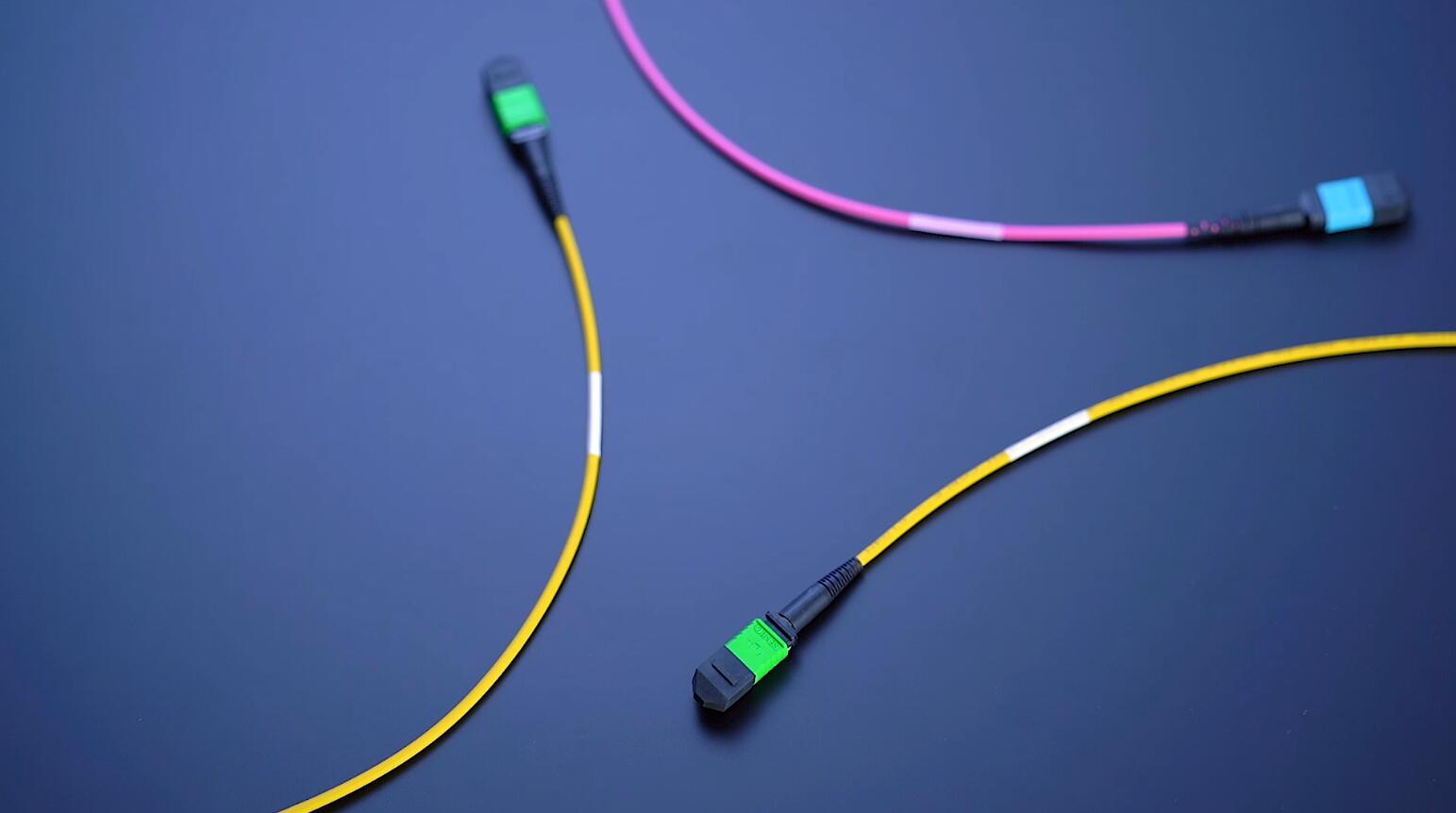
MTP/MPO trunk cable is a cable with two MPO or MTP connectors at both ends, with nothing different from ordinary patch cables seen from outside. However, the truth is that the cable usually accommodates 12, 24, 48 and even 72 fibers, and the ends are terminated with 12-fiber or 24-fiber MTP/MPO connectors according to customer’s choice. FS MTP/MPO trunk cables are designed for high density application which offers excellent benefits in terms on site installation time and space saving. They are available in multiple lengths and in single mode, multimode OM1, OM2, OM3 or OM4 with LSZH or PVC Jackets. With BIF, FS MTP and MPO cables are designed for improved bend performance in reduced-radius applications such as residential or office environments which have less bend sensitivity.
MTP/MPO Harness Cable
MTP/MPO harness cable is also known as fanout cable or breakout cable as it has a single MTP connector on one end and on the other end it breaks out into 6 or 12 connectors (LC, SC, ST, etc.). As one fiber patch cord contains two fibers for receiving and transmitting, a 8-fiber MTP-LC harness cable, for example, has 4 LC connectors and a MTP connector at either end. Similarly, a 12-fiber MTP-LC harness cable has 6 LC connectors and a MTP connector. MTP/MPO harness cable is usually deployed for 40G to 10G transmission and 100G to 25G transmission.

MTP/MPO Conversion Cable
MTP/MPO conversion cable has the same fanout design like the MTP/MPO harness cable, but it is terminated with MTP/MPO connectors on both ends. However, the MTP connectors on each end are different in fiber counts and types, which can provide more possibilities for the existing 24-fiber cabling system. It eliminates the wasted fiber, and therefore can largely increase the capacity of the existing 12-fiber and 24-fiber MTP network.
How to Deploy MTP/MPO Cables in 10G/40G/100G Connections?
Follow with the MTP/MPO fiber cables are the MTP/MPO cassettes, MTP/MPO fiber adapter panels and MTP/MPO breakout panels. Here are some typical applications of MTP/MPO fiber cables in 10G, 40G and 100G connections.
10G-10G Connection
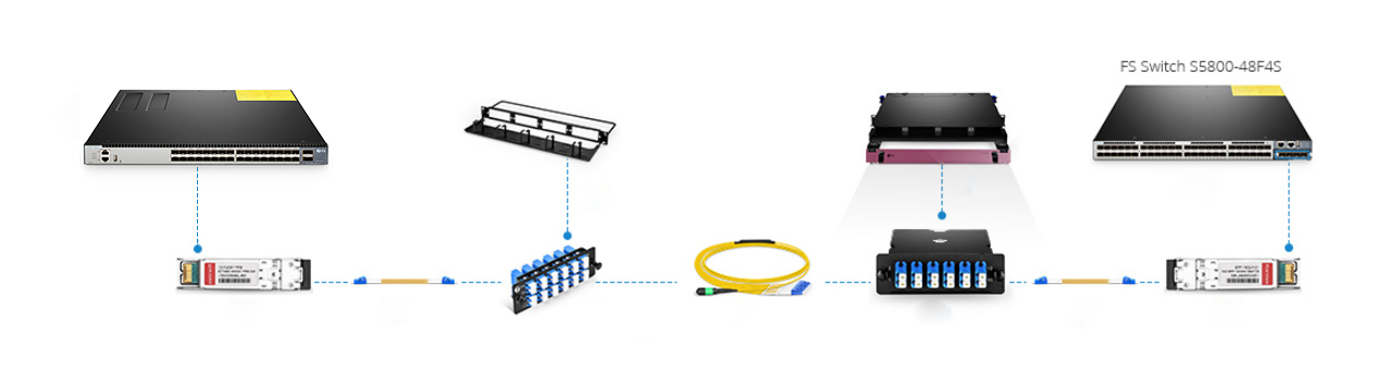
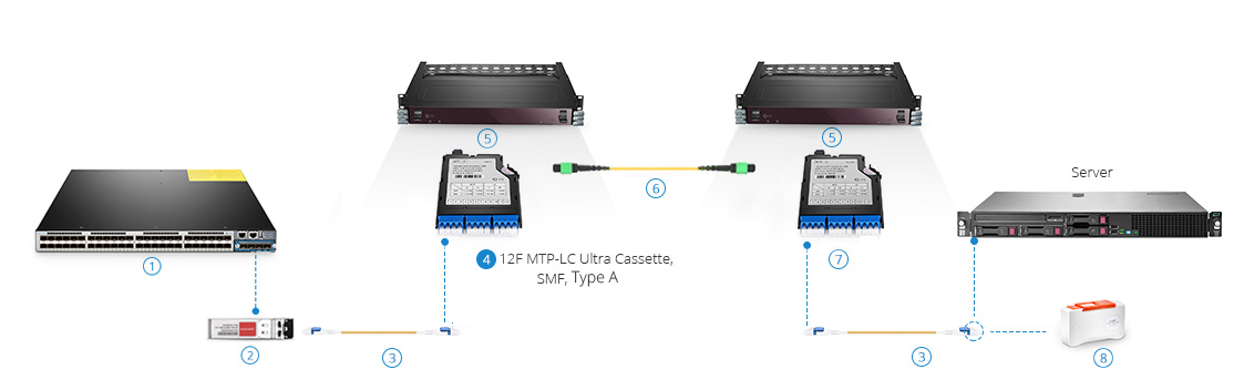
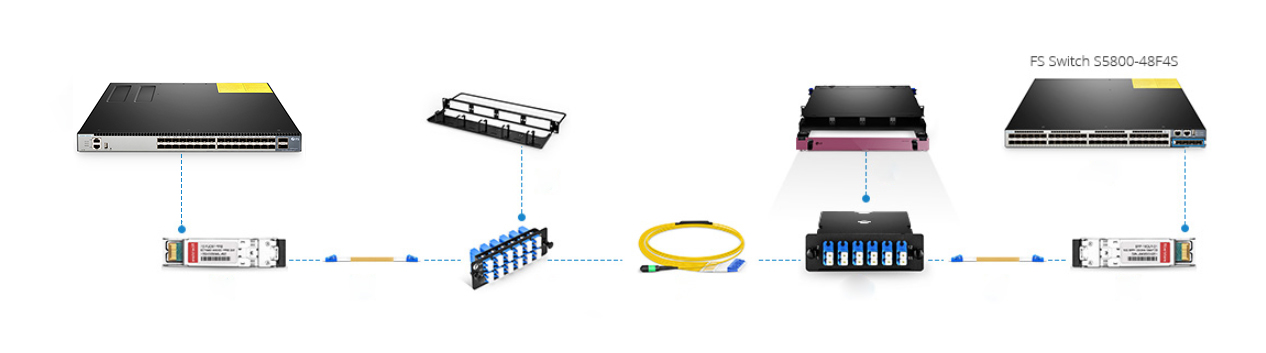
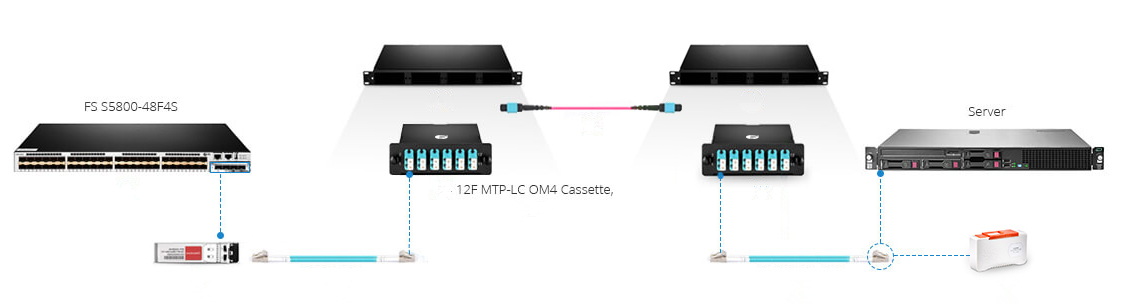
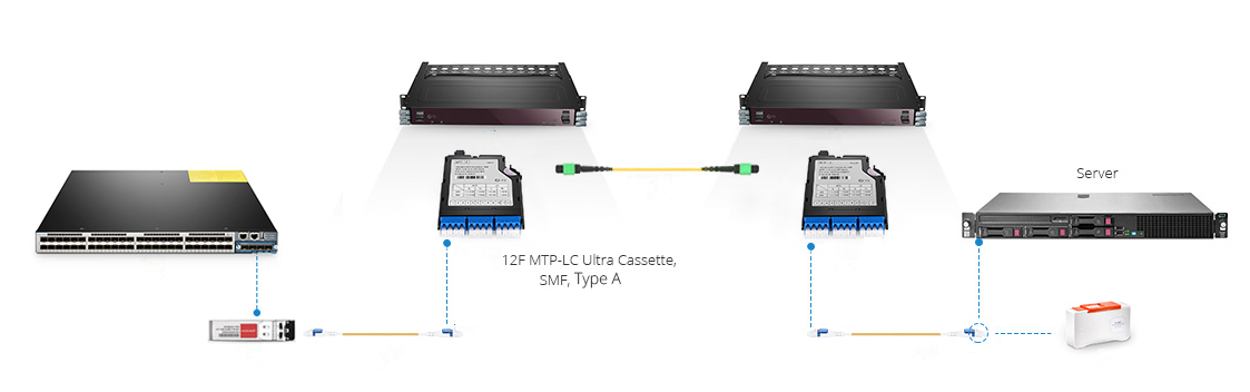
In the following two scenarios, two MTP/MPO cassettes installed in the fiber enclosures are connected by MTP/MPO trunk cables, making the core of the cabling simpler. The front panel of the cassettes is connected upwards to server and downwards to 10G ports of FS S5800-48F4S via OM4 fiber optic cable and 10G transceiver.
40G-10G Connection
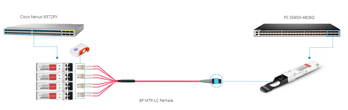
In this scenario, a 40G QSFP+ port on the FS S5850 48S6Q switch is split up into 4 10G channels. A 8-fiber MTP-LC harness cable connect the 40G side with its MTP connector and the four LC connectors link with the 10G side.
40G-40G Connection
As shown below, a 12-fiber MTP trunk cable is used to connect two 40G optical transceivers to realize the 40G to 40G connection between the two switches. The connection method can also be applied to 100G-100G connection. 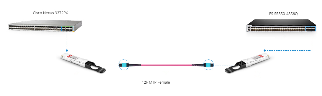
120G to 3x40G Connection
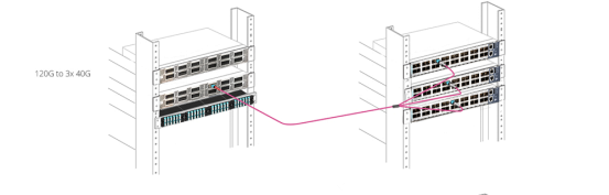
In this figure, a MTP/MPO conversion cable connects a CXP 120G SR12 and three 40G QSFP+ SR4 fiber optic transceiver modules to realize the migration from 120G to 40G networking.
Conclusion
High performance, high density MTP cable and MPO cable solutions can swap up to 12 traditional fiber connectors with one single small form factor connector, reducing installation time and labor costs. They are suitable for a variety of applications including data centers, telecommunications, broadcast communication, and server rooms. FS strives to provide you with best products with reasonable price and best service.
Related articles: Understanding Polarity in MPO System
Type A MTP Cassette and Type B MTP Cassette: When and Where to Use?
Fanless 24-Port Gigabit Switch Recommendation
Recently, many people have jumped on the bandwagon to use the 24-port Gigabit managed switch with advanced administrative controls. In particular, 24-port switch with PoE technology provides people with great convenience. However, the more power it sustains, the noisier it is. Have you been hassled by the endless noise or interrupted in your work? It is time to put an end to work frustration with fanless 24-port Gigabit switch.
What’s the Magic with Fanless 24-Port Gigabit Switch?
A Gigabit Ethernet switch without fan doesn’t mean that it does not have cooling system. Instead, it adopts a passive cooling system which achieves high level of natural convection and heat dissipation by a heat spreader or a heat sink to maximize the radiation and convection heat transfer modes. The passive cooling makes your switch dumb but not numb, as it still works efficiently. In a word, fanless switch is the most suitable in silent and energy-saving environments. Here introduce three distinctive fanless 24-port Gigabit switches.
Fanless 24-Port Gigabit Switch Recommendation
FS 2800-24T4S Fanless 24-Port Gigabit Switch
S2800-24T4F 1000Base-T switch features 24-port 100/1000Base-T ports and 4 combo RJ45 SFP ports that enable user to mix fiber and copper cabling on a single switch. This 24-port Gigabit fanless switch is designed to meet the demand of cost-effective Gigabit access or aggregation for enterprise networks and operators. It adopts high performance processor to provide full speed forwarding and line-dormant capacity to offer customs multitudinous service features. In addition, S2800-24T4F supports multiple configuration modes to make it easy for network management and maintenance. This switch comes with a four-year limited warranty, including any quality problems during the free maintenance.
HP ProCurve 1800-24G Fanless 24-Port Gigabit Switch
The ProCurve Switch 1800-24G is a 22-port 10/100/1000 switch with 2 dual-personality ports for RJ-45 10/100/1000BASE-T or mini-GBIC fiber Gigabit connectivity. This fanless switch is managed via an intuitive Web interface, ideal for deployment in open offices or homes that require silent operation. It can be mounted on a desk, shelf, wall or in a rack cabinet. However, the demerit of this 24-port gigabit switch is that it doesn’t possesses stacking port.
FS 3900-24T4S Fanless 24-Port Gigabit Switch
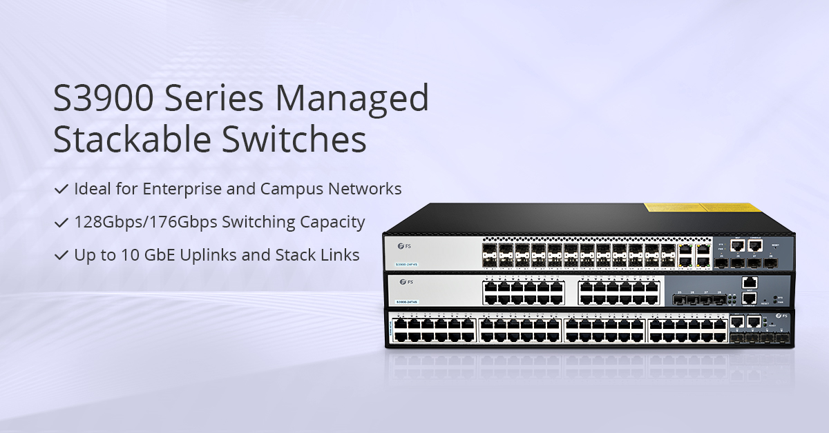
FS newly-released S3900-24T4S 10/100/1000BASE-T 24 port Gigabit switch comes with 4 10GE SFP+ uplinks ports. Since its debut, it has gained a lot of attention by its multifunction. As an advanced layer 2 Plus (layer 3 Lite) Gigabit managed switch, it supports stacking with 10G uplinks. In addition, the S3900 24-port gigabit stackable switch offered by FS boats an user-friendly web interface which makes it a snap to configure ports. An industry-standard command-line interface (CLI), accessed through the console port or Telnet, helps simplify the setup and operation of the network. The S3900-24T4S 24-port managed switch is almost an omnipotent switch for choice under many circumstances.
Conclusion
Kill the noise, and attend to your work. Fanless 24-port Gigabit switch ensures noiseless operation and increases the reliability and energy efficiency of the system. Listening to the voice of customers to understand customer issues, FS, a network solution provider, strives to provide innovative and professional solutions for you.
Related Articles: Should You Buy a Fanless Switch or Switch with Fan?
Necessary Tips for Fiber Optic Cable Installation
FTTH, the concept that has been hotly debated by people in recent years, drives the demand for fiber optic cables and its related products. However, fiber optic cable is fragile and hard to splice, which is worthy of consideration before installation. To make good use of fiber optic cable, well-organized fiber optic cable installation is a necessity.
Fiber Optic Cable Introduction
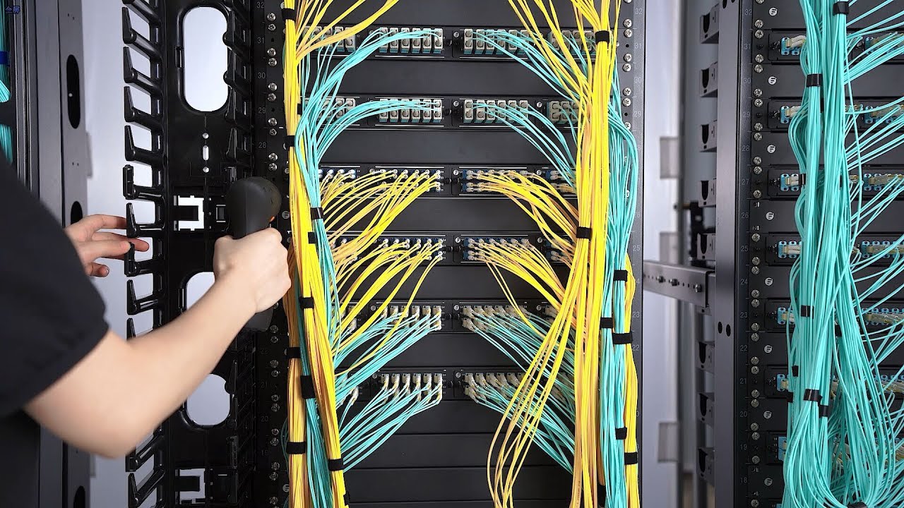
Fiber optic cable is a technology that uses small threads made of glass or plastic (fibers) to transmit data. However cheap and light it is, the material brings a troubling problem in fiber optic cable installation. It is an assembly similar to an electrical cable while the former one carries light and the latter carries electricity. Normally, fiber optic cable comes in two types, namely, single mode fiber (SMF) and multimode fiber (MMF). Single mode fiber is suitable for long distance data transmission while multimode optical fiber is used in short distance transmission such as computer network linking. Regardless of fiber optic cable types you use, it is necessary to maintain a good fiber optic cable installation.
Benefits for Good Fiber Optic Cable Installation
Good Working Performance
Good fiber cable installation ensures the highly effective and smooth working of the fiber optic cables. The cables can not only conduct high-speed signal transmission, but also carry more bandwidth. Moreover, if operate inside a large building or fiber optic home wiring, the signal will be strong everywhere in each room, for the fiber optic cables can carry strong signal strength over long distances.
Less Maintenance and Repairs
There’s nothing more annoying than a frequently breaking down cable system. A good fiber optic cable installation can spare you a lot of energy in the future maintenance and repairs, preventing endless frustrations. As for making a good structural installation plan, there are many things to consider. The next part will shed light on fiber optic cable installation guidelines.
Guidelines for Fiber Optic Cable Installation
Fiber cable installation can be categorized into different types, namely aerial fiber installation, direct burial installation, underground duct installation and household fiber cable installation. Regardless of the cabling condition, bear in mind the following guidelines.
Start with proper planning so as to avoid mistakes and problems. Inspect the route before cable installation, detect the possible problems and get the solutions. Decide the number of cabling and connections needed. Moreover, we’d better consider planning ahead for installing additional cabinets, servers and network components.
Test every fiber optic cable before and after the installation. For, example, use visual fault locator to find breaks in fiber cable. Make timely replacement or repairs to guarantee the normal installation process.
Do not bend or kink fiber cables. Never exceed the cable bend radius of the fiber patch cord. These will harm the fibers. Use necessary tools to maintain a minimum bend radius of the installed fiber optic cable. Another way is to use bend insensitive fiber cables. Some vendors like FS provides BIF fiber patch cord of 10mm maximum bend radius, which is more flexible in cabling.
Do not mix or match varied core sizes. Here recommends cable ties to bind the same type of cables together in case of confusion. Cable labels also can be used to mark different cables for easy identification.
Use proper tools and techniques. Tools such as fiber patch panel, cable management panel can keep a well-organized cabling. And fiber enclosures can protect cables from external damage and are dust-proof. Fiber raceway can be installed overhead to route and support the cables. FS highly trained and skilled experts specialized in data cabling installation and fiber optic cabling installation are equipped with the necessary tools to create both permanent and temporary joints between fibers according to fiber optic cable installation standards.
Conclusion
It is undeniable that fiber optic cable is worthwhile trying. However, do not follow suit to buy what you actually don’t need. Make clear of its advantage and figure out the fiber optic cable installation. First and foremost, read through this article.
Related Articles:What Is Fiber Optic Cable and How Does It Work?
How to Configure DHCP for Multiple VLANs?
Almost every device connected to the Internet needs an IP address. Previously, the countless IP addresses are assigned manually, which costs a lot of time and energy. As DHCP emerges, IT specialists are not required any longer to spend countless hours providing IPs for every device connected to the network device. But what is DHCP? How does it work and how to configure DHCP for multiple VLANs?
What Is DHCP?
DHCP – Dynamic Host Configuration Protocol is a network management protocol used on TCP/IP network. There may be at least a DHCP server and many DHCP clients. The DHCP server allows the client to request the IP addresses and other network configurations from the Internet service provider. This process eliminates the need for administrators or users to assign IP address to network devices one by one. Using this protocol, the network administrators will just set up the DHCP server with all the additional network information, and it will do its work dynamically. Both network switch and router can be configured as a DHCP server.
How Does the DHCP Process Look Like?
For the DHCP client that hasn’t accessed the Internet before, it will undergo 4 phases to connect the DHCP server.
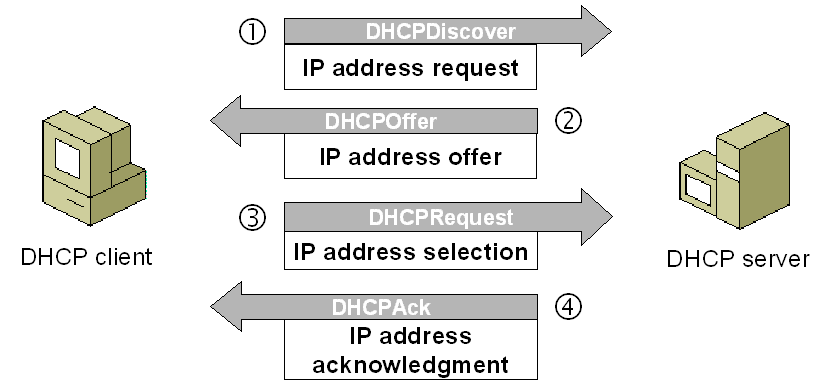
Fig 1. DHCP process
1.Discover
DHCP client after being activated will first send a broadcast message to try to look for DHCP servers. In this way, the client request IP address from the DHCP server.
2.Offer
When the DHCP server gets the message from the client, it looks in its pool to find an IP address it can lease out to the client. It then adds the MAC address information of the client and the IP address it will lease out to the ARP table. When this is done, the server sends this information to the client as a DHCPOFFER message.
3.Selection


DHCP client chooses IP address. There may be several DHCP servers sending DHCP-Offer packet, the client only receives the first DHCP-Offer then sends back DHCP-Request packet in broadcast mode to all DHCP servers to request more information on the IP address lease time and verification. The packet includes the contents of the IP address requested from the selected DHCP server.
4.Acknowledge
When the DHCP server receives a DHCP-Request packet from the DHCP client, it confirms the lease and creates a new ARP mapping with the IP address it assigned to the client and the client’s MAC address. And then send this message as a unicast to the client as a DHCPACK.
How to Configure DHCP for Multiple VLANs?
The theory cannot be well digested unless it is combined with the practice. In this section, how to configure DHCP for multiple VLANs is introduced for your reference. Take the following picture as an example.
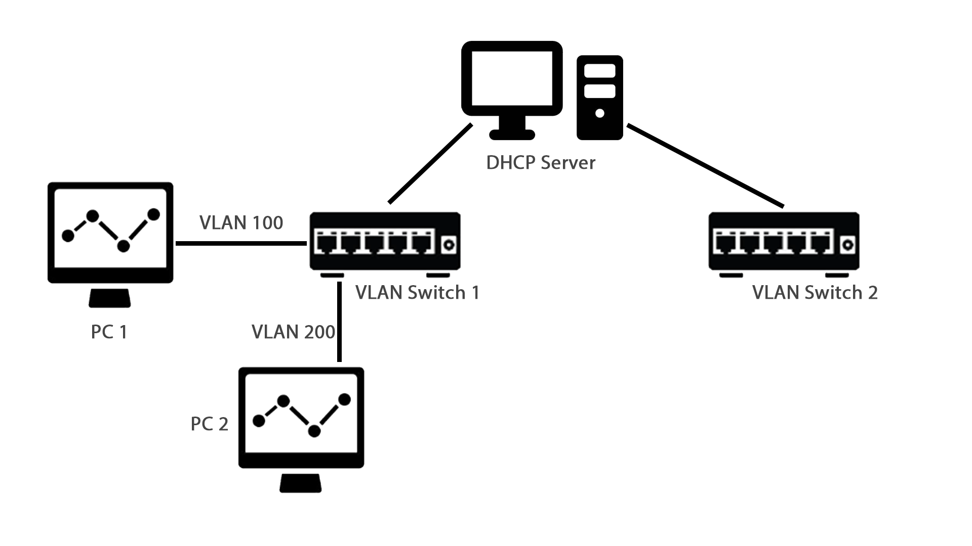
Fig 2. DHCP Configuration for Multiple VLANs
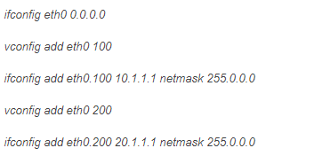
PC1 and PC2 are connected to access port of VLAN switch 1 with VLAN ID 100 and 200. The DHCP server was supposed to serve both the VLANs.Command to enable multiple VLANs.
Command to enable DHCP.
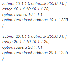
Add both subnets.
Run DHCP server.
Now make PC1 and PC2 as DHCP client. Both should be able to get IP address from DHCP server in their respective VLAN.
Conclusion
How to configure DHCP for multiple VLANs? This issue has been illustrated in the above content. DHCP configuration is worthy of being learned by those who are engaged in fiber optic communication field. You just need to know “How”, and let FS provide you with the best network devices. Ethernet switch like gigabit Ethernet switch and 10gbe switch, and routers are available in FS.